 iTTL Metz 45 to Arduino Conversion - Nikon Protocol
Metz SCA 3000 interface for Metz45
Many years ago, I was very sad discovering that my 45 CL4 from Metz will not work anymore with Nikon D7000. The SCA3000C and SCA3402 do not manage properly the A or M mode of the 45CL-4 and no TTL!
Then, recently due to COVID context, I decide to reopen this project. After 30 days of work here is the interface, the I-TLL internals and also the reason why Metz did not produce this interface.
The 45 CLx is thyristor based technology (to stop the flash) and it is not sufficiently rapid to respond to i-TTL pre-flash sequence. It is the main reason why they develop the 45 CL digital. Otherwise, easy to use A and M mode and also i-TTL with AEL (permit to introduce delay between pre-flash and main strobe).
Target of the project
Using an empty Metz SCA3401 shoe, Teensy micro CPU board and SCA3000 M1 cable, I interface the flash 45CL-4 (or CL-3) flash with D7000, D7100 DSLR with following features:
- i-TTL protocol management using Mode A,M,TTL BL and TTL
- Mode A without pre-flash.
- TTL and TTL BL selection per switch on the SCA shoe
- Exchange with DSLR to report in view finder (and info on rear panel):
o flash ready
o flash mode (selected on the flash disk on top of the head)
o Automatic selection of the speed (native when i-TTL active)
- Pre-flash and power management from 1/128 to 1/1
- AEL capability
- Synchronization 1st or 2nd curtain
- Low sync capability
- AF assist led of SCA shoe manage from DSLR (even if I never use it)
A Push button permit to send a test flash in all modes (in TTL 1/128 of the power).
Limitation: No HSS mode, No modeling (impossible to modulate the light at the required speed).
Today the target is reached except the limitation to use TTL BL ( or TTL) for direct shoot. Could be used only with AEL (Fn ou Pv button). To use the TTL BL with no restriction, the electronic of the 45CL must be modify replacing 1 thyristor per an IGBT. The current limitation is 100mS delay between each strobe. Need to be less than 50ms for TTL pre-flash. For Modeling and HSS they use 50µS pulse at a frequency of 70Hz (14,5 mS period). Could be done with IGBT but this is another story.
 I am happy with the power and light quality of
this flash gun. It is now back in my photo toolkit.
I am happy with the power and light quality of
this flash gun. It is now back in my photo toolkit.
Hardware interface with Metz 45 CL
20 or 30 years ago, I investigate this interface. You have 6 signals, 2 permit to manage the flash and others to read the setup and status:
- Mode is an analog signal, voltage level depending of the selected mode and aperture in A mode
- Start and stop signal, flash ready, flash power supply, etc..
To simplify the execution, I decide to adapt the SCA3000 M1 cable that use TTL signal on computer side and includes appropriate interface with flash signal (0-18V):
- Diode on Ready signal
- Power converter 7V to 5V to replace the 4 AA battery used in SCA3000 C
- Flash test button
The battery of the 45CL3 or CL4 is small and limit. I always use this flash with Quantum Turbo battery or Quantum Battery 2 smaller and lighter. This is another discussion.
I-TTL protocol.
The main problem of the project is to decode and understand the i-TTL protocol and three layers:
- Hardware exchange between DSLR and Flash (Bus signal)
- Message exchange between DSLR and Flash or flash and DSLR
- Execution of the different command.
I started investigation based on information on the web that describes some message exchange and it gave me an idea of the problem. After analyses and test, here a description of the i-TTL protocol.
Message Exchange and Message List
Messages are exchanged using Frame of bytes (8 bits word). Each Frame staring with Command code “Cmd” following with information byte(s) when needed.
Cmd list:
Device capability:
0xA1 + 17 bytes + Checksum. Flash type
Sent by flash after wake up (data out)
Camera answer « camera type »
0XB1 + 9 bytes + Checksum. Camera type (data in)
Sent by camera after « flash type » during init phase (1st exchange)
0xA2 + 45 bytes + Checksum, Flash capability
Sent only 1 time after camera type (if no error; otherwise restart A1 B1, etc…)
Device status - setup
Permit to exchange current setup and parameters between DSLR <-> Flash (bi directional)
It is a kind of watch-dog dialog. DSLR initiate the exchange sending cmd B0, the flash answer to A0 command. This occurred every 50ms.
0xB0 + 14 bytes + SUM, DSLR setup,
Flash answer with « flash status »
0xA0 + 22 bytes, Flash setup and status
flash command
Command from camera to flash
PreFlash
0xD7 no additional byte. The minimum power pre-flash
When the flash fires clock goes low during flash light activation to acknowledge the command.
PreFlash 30
0xD8 + 0x18, (pre flash with 30% more power – see part 3 – updated in may 2020)
When the flash fires, clock goes low during flash light activation
Power command
0xD3, + 3 bytes 0x10, 0xPP, 0xD3. Main flash power command
The PP is anything from 0x58 to 0x7F,
The last byte is sent by flash to DSLR as acknowledge.
Power is manage per 1/12 IL from 1/128 to 1/1 (in case of the SB-900)
Modeling (or Pilot Lamp)
0xD5 no additional byte.
(Must be investigated and confirmed) first Cmd received: Start, second stop.
Red eyes reduction
0xD1, + 1 byte data ( 3 flash at 250 mS period; managed by flash itself)
0x80 on
0x00. off
AF assist
0xD0 + 2 bytes. Total 3 bytes
Sent every 50 mS (for on), one time at the end for off command
1st Byte: 0 AF assist off; 1 AF assist on
Frame sample:
0xD0, 0x01, 0xF0
0xD0, 0x00, 0x00
Sync X signal start flash strobe (Hardware trigger, no protocol command but activate data signal before next frame)
When receive Sync signal, Flash could assert data signal to 0 during 2,8 to 3mS to avoid any glitch then release (Input Pull up)
No signal on clock. The body acknowledge with Data signal asserted low during several millisecond with no other signal. Then next frame transfer will be initiated.
Other command exists (Master of Controller mode, 0xD4, 0xD9, 0xDA, 0xDB, 0xDD,) but not reported there (investigation needed and out of scope of this project).
Auxiliary frame
Standby
0xE0 + 2 bytes. Total 3 bytes
1st byte data: 00 Standby 01 DSLR off
Illumination level
First frame sent by DSLR after sending main Strobe (Sync X activated).
0xC0 + 5 bytes. Total 6 bytes
Data bus transfer
Data direction
The Data bus is only one line and Data direction In or Out. Then the way it is manage is quite simple and not magic.
The frame are predefine and if the DSLR body initiate all transfer sending the Command byte, the following byte could be provided or by the DSLR body, or by the flash. This is also predefined for each frame.
0xAn command Data send by Flash
Others 0xBn, 0xCn, 0xDn, 0xEn Data send by DSLR except last byte of 0xD3 command (see error control here after).
Error control
To control the transmission and detect possible error, different strategy are implemented:
The long frame like capability and status are terminated by a checksum. If checksum is wrong, the frame is ignored and/or protocol could be reinitialized.
Short frame command must be acknowledged at hardware level asserting “Clk” low. This is the case of Pre-flash command : Clk is activated during pre-flash strobe.
Specific case for Power command 0xD3. If the first 4 bytes are sent by DSLR, the last one is sent by flash as acknowledge. If not received (in case of de-synchronization) the command is ignored and following command not sent (in TTL BT, AEL will not work; if main shot, the main flash will not start).
Bus Level
The Bus is 0-5V TTL level but many of the equipment, DSLR of Flash, use 3.3 V level during exchange. Then interfaces must be 0- 3.3V compatible 5V.
Data Exchange – Bus transfer initiation
Principle:
Device synchronization is necessary to sync software and device state machine and insure proper exchange. Data and handshake are used during this phase to initiate 1st byte transfer of a frame.
After device synchronization data are exchanged using handshake and clock.
- Handshake controls all data exchange. Output from DSLR
- Clock always produced by flash
- Data is bi-dir depending of the situation.
When handshake is activated, Flash produce CLK signal and DSLR send Data synchronously.
The command defines:
- Data direction for bytes following the command byte
- Byte quantity
- Task to do
 Frame Transfer initiation
When no flash or flash power-off camera activates Data signal every 50 mS. Pulse down during 360uS.
Flash wait Data signal low. Flash initiate frame transfer maintaining Data low until DSLR activates Handshake. Then flash releases Data (data in) and waits Handshake low with additional small delay to initiate clock and associated byte transfer. For next byte of the frame, handshake is directly activated by DSLR.
 Each time a new frame is exchange, same
hardware protocol to insure proper synchronization and resynchronization in
case of error
Each time a new frame is exchange, same
hardware protocol to insure proper synchronization and resynchronization in
case of error
When the camera and flash start i-TTL protocol, the communication always follows the sequence describe here upper whatever is the situation: flash on first, body on first.
This is the transport level synchronization. Then enter the frame exchange to initialize the protocol until full activation. During initialization of the protocol, the two devices exchange following frame:
« Flash type », « camera type », the capabilities of the devices
0xA1 + 18 bytes, 0XB1 + 10 bytes, 0xA2 + 46 bytes,
0xB0 + 15 bytes, 0xA0 + 22 bytes, the current setup/params
... Repeat of "0xB0 + 15 bytes, 0xA0 + 22 bytes" every ~50ms.
Or
0xA1 + 18 bytes, 0XB1 + 10 bytes,
0xB0 + 15 bytes, 0xA0 + 22 bytes, 0xA2 + 46 bytes,
... Repeat of "0xB0 + 15 bytes, 0xA0 + 22 bytes" every ~50ms.
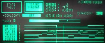
Example of frame sequence when body and flash in standby and you decide to shoot:
Mode I-TTL BL – D700 and SB-900
Cde:A1,1,1,5,2,8,7,81,78,B4,64,A,4E,FF,3E,90,3E,90,1D
Cde:B1,2,1,19,4,3,1,9,1A,E,7
Cde:A2,3,5,6D,9B,90,86,80,7A,72,6A,65,5E,6,75,9E,94,8A,80,77,6F,66,60,58,6,74,9E,95,8B,80,76,6F,66,60,59,4,5F,96,8A,82,80,7E,79,71,6E,6A,FC
Cde:B0,5,0,40,FF,0,0,50,0,2,5C,22,0,FF,FF,C3
Cde:A0,3,1,C0,4,0,0,92,5E,30,4B,0,FF,FF,0,0,0,0,0,0,0,0,32
Cde:B0,5,44,40,2A,24,1E,50,2,2,5C,22,1E,2A,2A,EA
Cde:A0,3,1,C0,4,0,0,92,5E,30,4B,0,FF,FF,0,0,0,0,0,0,0,0,32
Cde:D7
Cde:D3,10,6F,D3 Sync X is send there, after 0xD3 command.
Cde:C0,0,C1,A,7D,88
Cde:B0,5,40,40,2A,24,1E,50,2,2,5C,22,1E,2A,2A,E6
Cde:A0,1,1,C0,4,0,0,92,5E,30,4B,0,FF,FF,0,0,0,0,0,0,0,0,30
Cde:B0,5,44,40,2A,24,1E,50,2,2,5C,22,1E,2A,2A,EA
Cde:A0,3,1,C0,4,0,0,92,5E,30,4B,0,FF,FF,0,0,0,0,0,0,0,0,32
Cde:B0,5,44,40,2A,24,1E,50,2,2,5C,22,1E,2A,2A,EA
Cde:A0,3,1,C0,4,0,0,92,5E,30,4B,0,FF,FF,0,0,0,0,0,0,0,0,32
...
Cde:E0,0,E0 DSLR standby
Frame interruption
Command 0xD7 and 0xE0 could interrupt 0xB0/ 0xA0 recurrent exchange. This is mandatory to avoid delay when shooting. It must be manage when decoding the frame level.
Command execution
When a frame is completely received, the flash executes the command.
Power control of the flash
Nikon use a code that permit to control flash power per 1/12 IL from 1/256 to 1/1.
Command is : 0xD3, 0x10, 0xPP, 0xD3
In case of SB-900 The PP is anything from 0x54 to 0xA8 with 0x54 being minimum 1/128 and 0xA8 full power 1/1
Command details
will be describe in another post.
Tools
To do the analyses, I develop in parallel the i-TTL protocol manager for the flash a protocol analyzer based on Arduino software environment and its integrated debug Consol. The Protocol analyzer permits to send sync signal to trigger an external logic analyzer (Old HP logic analyzer). To terminate I use a traditional Scope to look at signal wave form.
Other documentation
Another document will be published with detail documentation about Protocol implementation to control Metz 45 CL-4 / CL-3 DSLR.
- design of the interface
- design of the software
- design of the power table
Hervé QUEVAL- Apr 21 2020 – updated in May 2020
Appendix 1
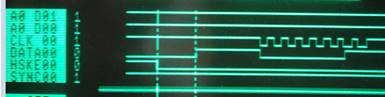 Clock data
and handshake
Clock data
and handshake
It is not a classical SPI bus because clock is provided by flash and DSLR initiate all frame.
Then we can say DSLR is master after hardware negotiation with Data line.
The camera begins data communication and toggles the handshake low, then the flash pulse the clock:
- 8 clock period per handshake, 32us each.
- Handshake active low
- Clock active low, data is read on the rising edge of the clock.
Data:
- The bytes are sent big-endian.
- The sender (camera of flash) sets data high for 1 and low for 0.
- Data provided by sender on the falling edge of the clock.
- Data must be read on the rising edge of the clock
Data direction
- By default data bus high Z (or input on both side).
- High level by pull-up on DSLR side, flash connected or not; DSLR on or off
- First byte of a frame is always sent by DSLR
- Flash decodes and decides if data line is in or out.

Clock is not only clock.
During flash strobe, clock is pull down for following cases:
- PreFlashMin
- PreFlash30
It indicates flash strobe activity to DSLR.
During hardware initialization (flash on and body off) the clock signal is pulsed regularly to detect the presence of the DSLR (SB-900). Permit to detect physical connectivity. At the moment seems that is it an implementation to assure compatibility with oldest Nikon devices.
Appendix 2
Arduino
software
Arduino
software to manage i-TTL protocol and Metz 45 CL-3 or CL-4 flash 45-iTTL_V0.ino
Do not need
particular library except Teensyuino environment.
Appendix 3
Command summary and related data (identified – non exhaustive list)
|
0xB1 |
DSLR identification |
Content unknown at this moment. Consider the frame as single object. |
|
0xA1 |
Flash identification |
Content unknown at this moment. Consider the frame as single object. |
|
0xA2 |
Flash capability |
Content unknown at this moment. Consider the frame as single object. |
|
0xB0 |
DSLR state and status |
Transmit to Flash: - ISO - aperture, shutter speed - lens focal - mode (PASM) - exposure compensation - selected flash mode - distance to the subject - FP activated - ack request (to clarify) - … (to be discovered) |
|
0xA0 |
Flash state and status |
Transmit to body: - flash ready - ack to body request - flash mode - flash level (in M mode) - exposure compensation (set on flash) - power available (average on a period) - … (to be discovered) |
|
0xC0 |
Luminance of the picture |
Transmit to flash the luminance level of the picture, bytes 3, 4 and 5 A 9x xx seems correctly exposed. 9 xx xx and less overexposed (to investigate)
|
|
0xD0 |
AF assist |
AF assist ON / OFF repetitive command to keep AF On |
|
0xD1 |
Red eyes reduction |
Activate / deactivate periodic short flash for red eyes reduction. |
|
0xD3 |
Set Power |
Indicate the power level to memorize and use for the Sync x command. |
|
0xD5 |
Modeling |
Start / stop modeling (50 µS flash pulse at 70Hz) |
|
0xD7 |
Pre flash |
Request a pre-flash at 1/128 |
|
0xD8 |
Pre flash 30% |
Request a pre-flash at 30% the power of the flash (must check the power level and confirm) |
|
0xE0 |
DSLR stopped |
01 Power off ; 00 standby |